An HK MP5 Reweld Done Right
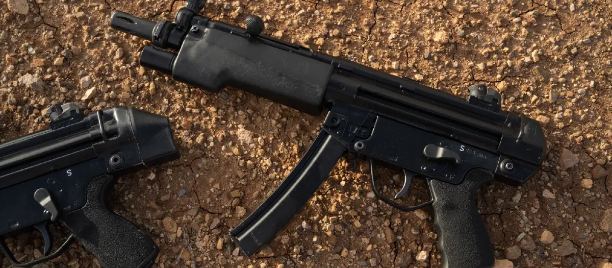
Hello everyone! If you search around for reweld builds, the results aren’t encouraging (in some cases, downright horrifying). With the right tools, doing a reweld on an MP5 (or other roller HK) is really pretty approachable. Thought I’d share a few thoughts as I build up these two torch-cut MP5s out for a customer while retaining the original magwell and front receiver stub. I’ll be using a new-manufacture flat for the rear end, as there isn’t much left of the original material past the magwell–so not technically a full reweld of all-original receiver parts, if one gets pedantic.
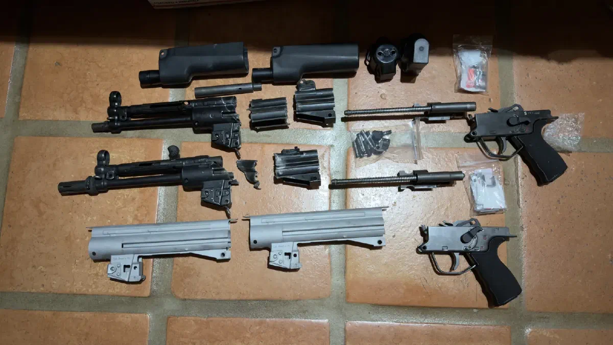
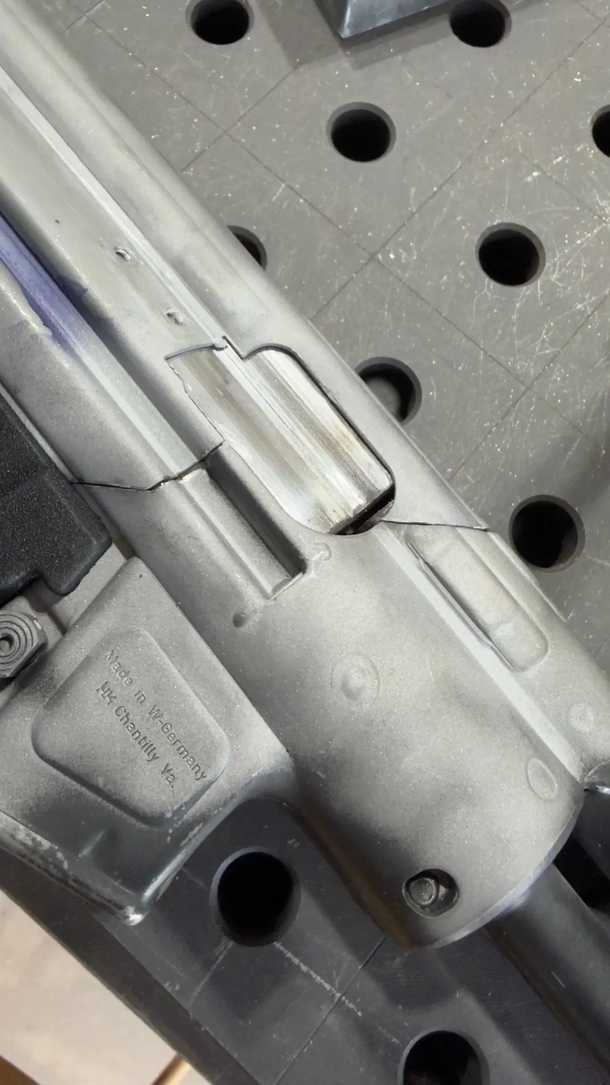
HK MP5s. Not much left of the receivers, but the front stub is good.
The customer provided pre-made Gigliotti receivers, which needed substantial work to be serviceable. Neither receiver passed the drop test, and the distance between internal rails measured 0.867 against a spec of 0.889 +.008. This is a full 0.22 undersize, nearly unusable. The idea behind a pre-welded HK clone receiver is to ameliorate the requirements for specialty forming and folding tools, but these receivers were so out of spec that they needed my mandrels to be reformed correctly. I do not recommend this manufacturer.
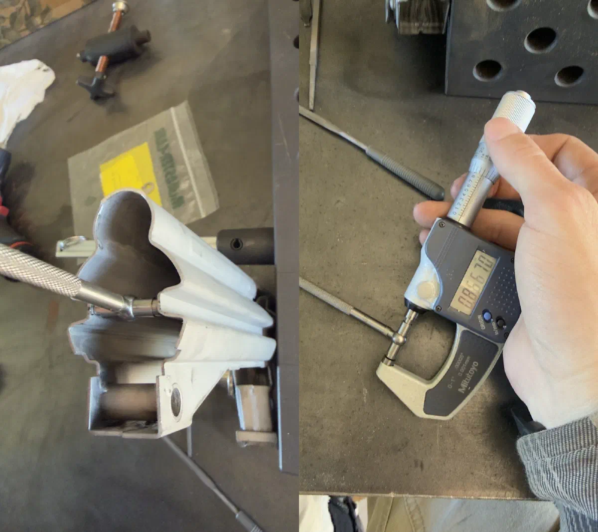
This is not what this is supposed to be.
I noted significant issues with the quality of the welding on virtually every seam. I won’t showcase every issue, since that’s not the point of this article, but I will make a few notes:
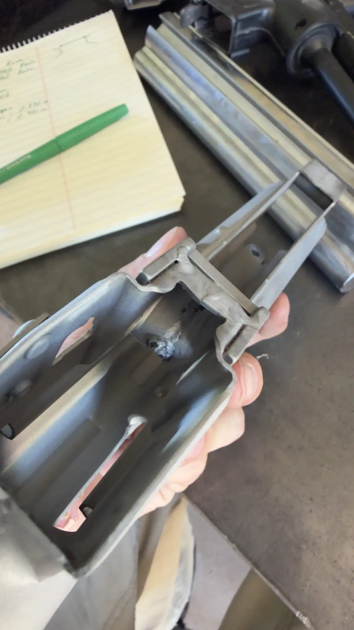
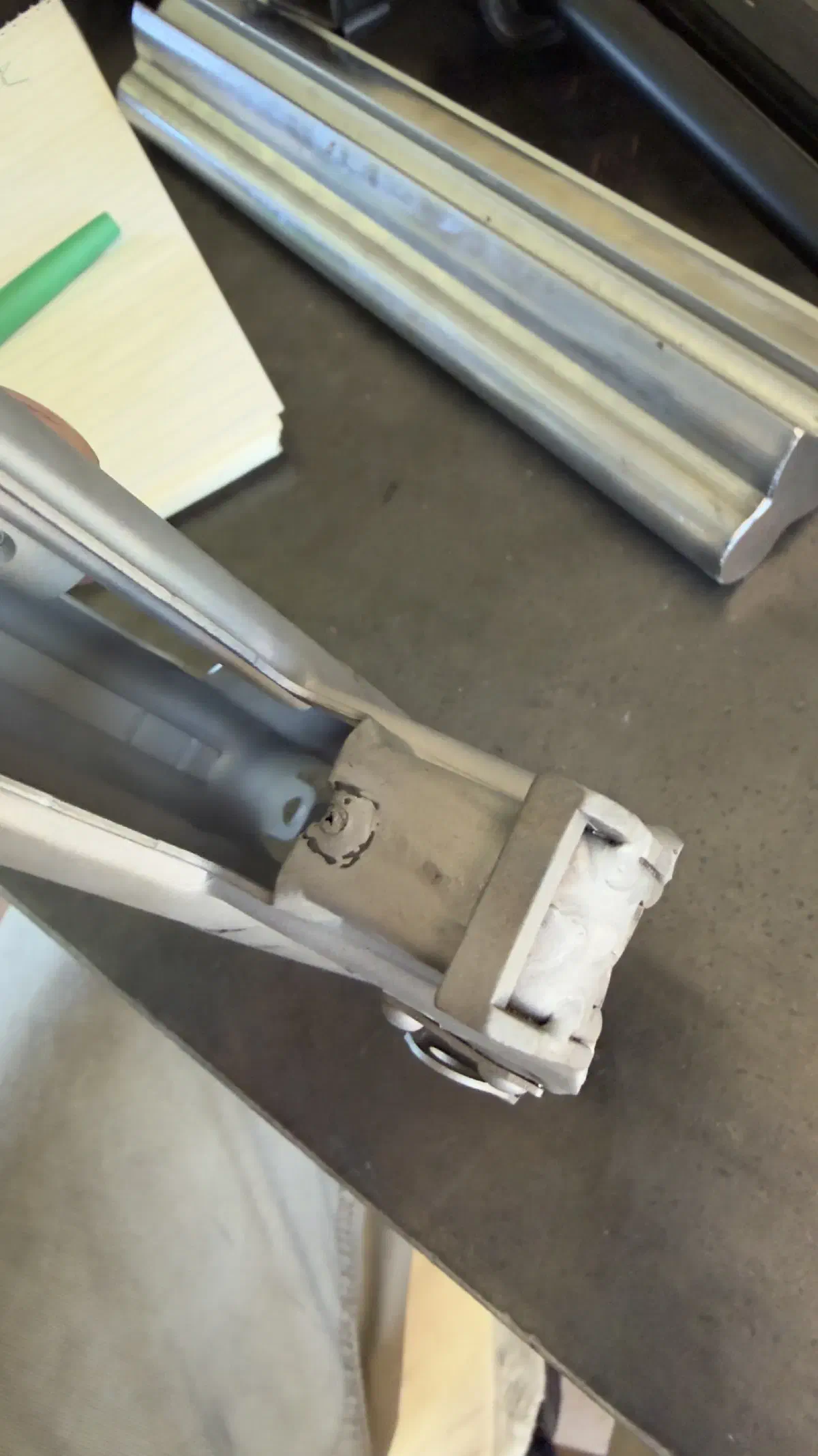
Rear seam showed severe burn-through and contamination. Metal was crudely filled with a MIG process, and clearly got the entire area very hot. This should not have passed QC.
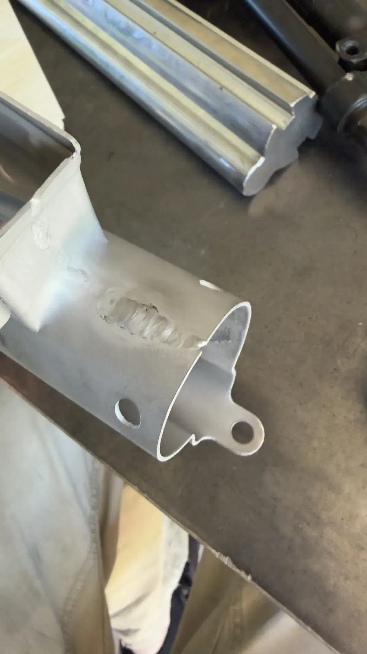
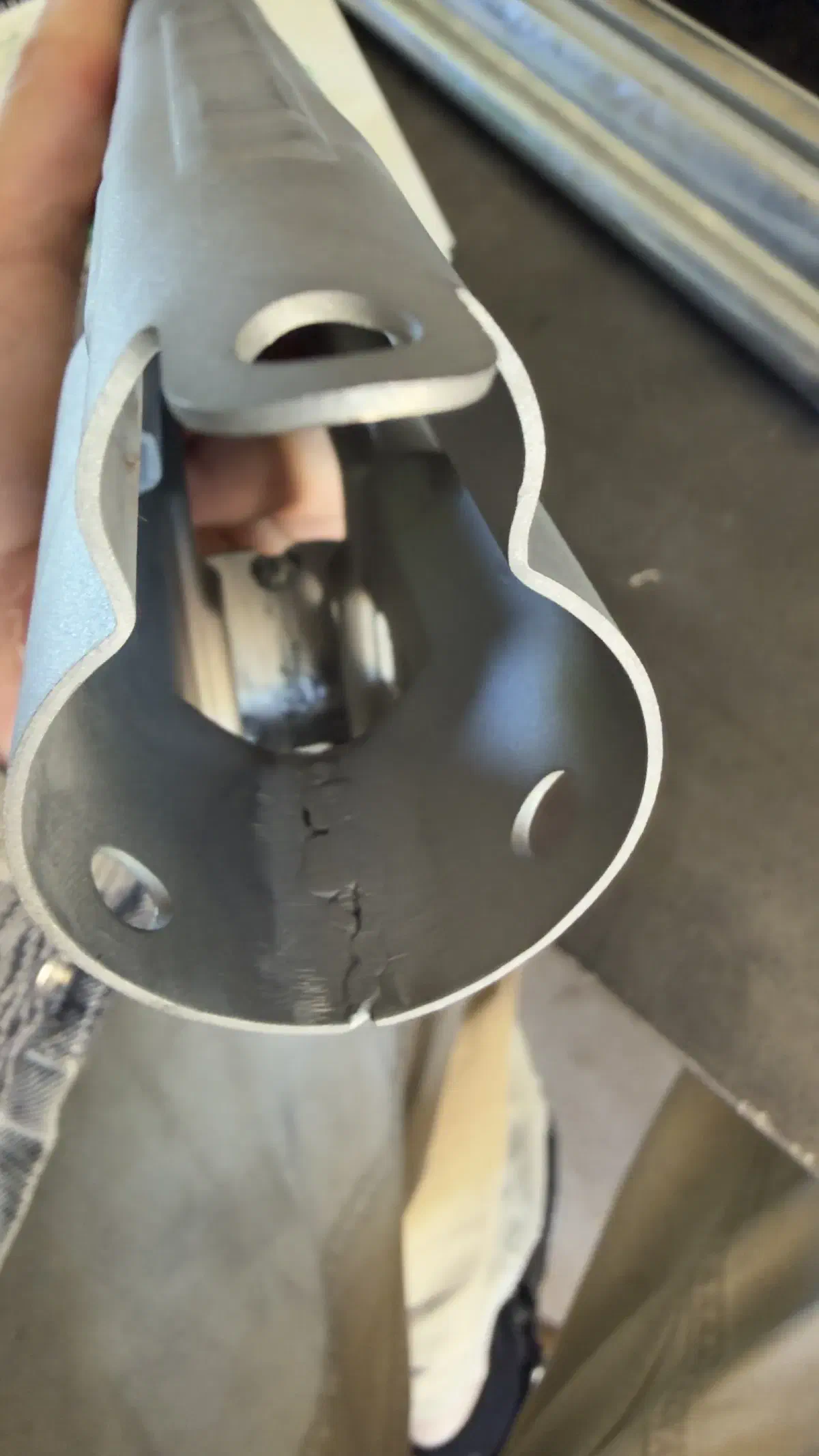
More burn-through “repaired” by dumping a ton of wire into the metal; some effort was made to dress the weld from the inside. A concerning mix of under- and over-penetration. Both receivers have these problems. Retraining is definitely needed for whoever is putting these together. A backer is clearly not being used, which is a bizarre decision for anyone in a production environment. I use backers on everything, and I make fewer than two guns a month.
Fortunately, we don’t need most of this receiver. The front end comes off.
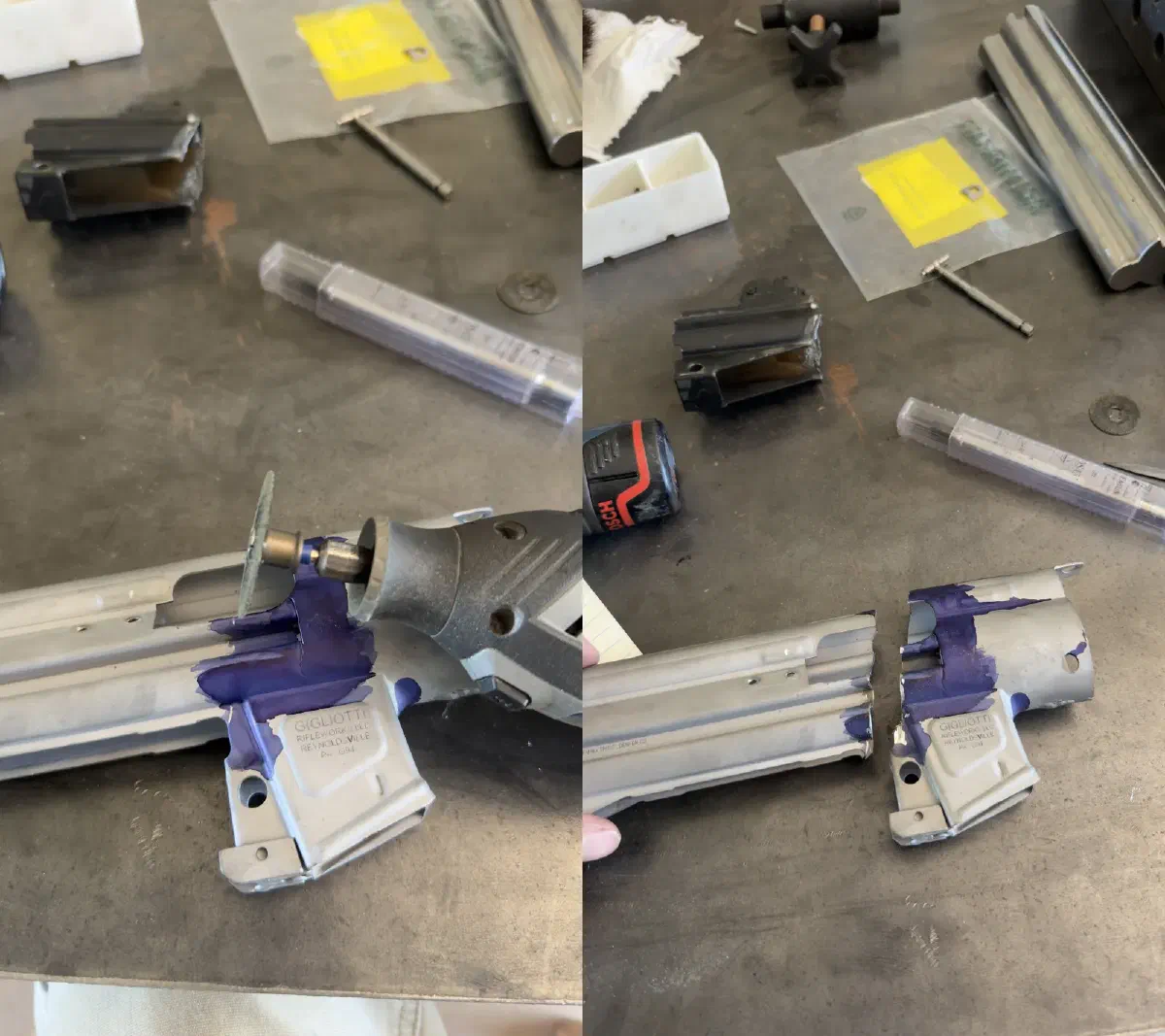
The front fell off!
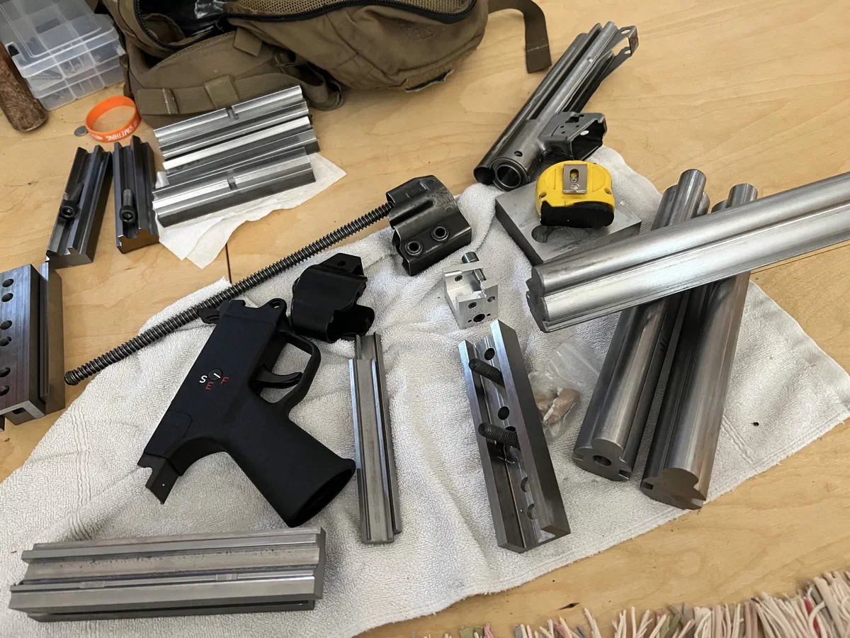
The stub is cleaned up, and the rear receiver section is cut to match. Both are placed on a billet 1018 mandrel of my design and manufacture. A cylindrical backer with an end that locates into the cocking tube is installed at the very front to provide a backer to the frontmost portion of the receiver above the trunnion on one of the guns.
I machined my mandrels out of billet 1018. 1018 is more than adequate for this application. 4140 (or god forbid, tool steel) simply isn’t necessary. If you want harder, then case harden your 1018 mandrel.
The mandrel+section assembly is clamped in a vise using my press dies and tacked.
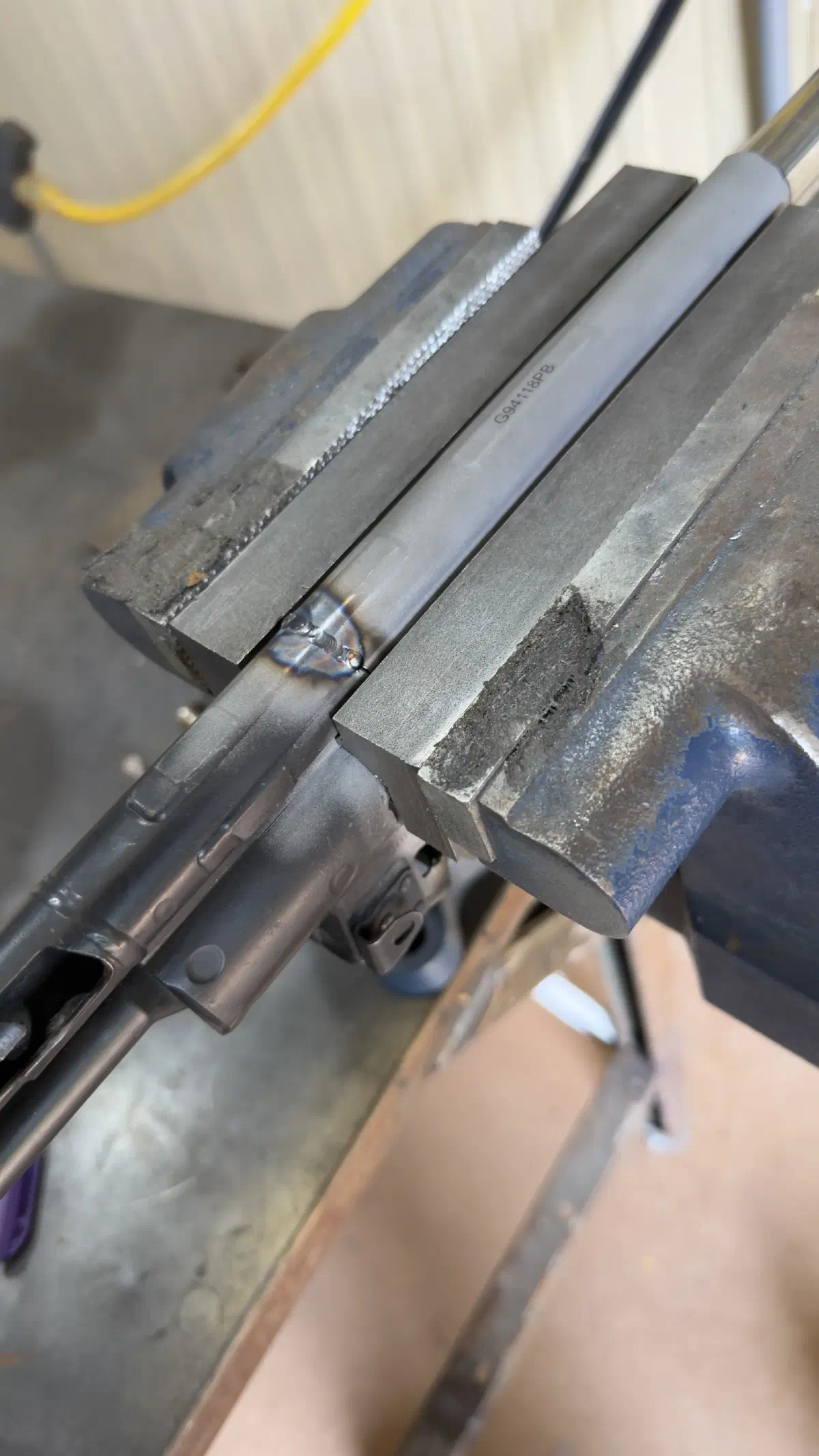
35A tacks; 45A beads to ensure full penetration.
The assembly is moved to the welding bench to work on the horizontal bits
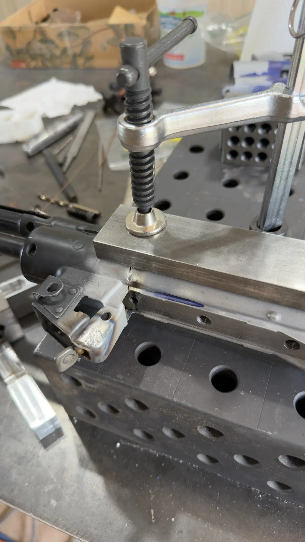
Using .045 ER70S-2 steel filler; I prefer it to 1/16 for this work.
Once all accessible areas are welded on either side of the press dies, the dies are removed to allow me access to the rest of the metal. Once again, 45A, moving quickly to ensure I don’t overcook the metal. I keep a close eye on my HAZ.
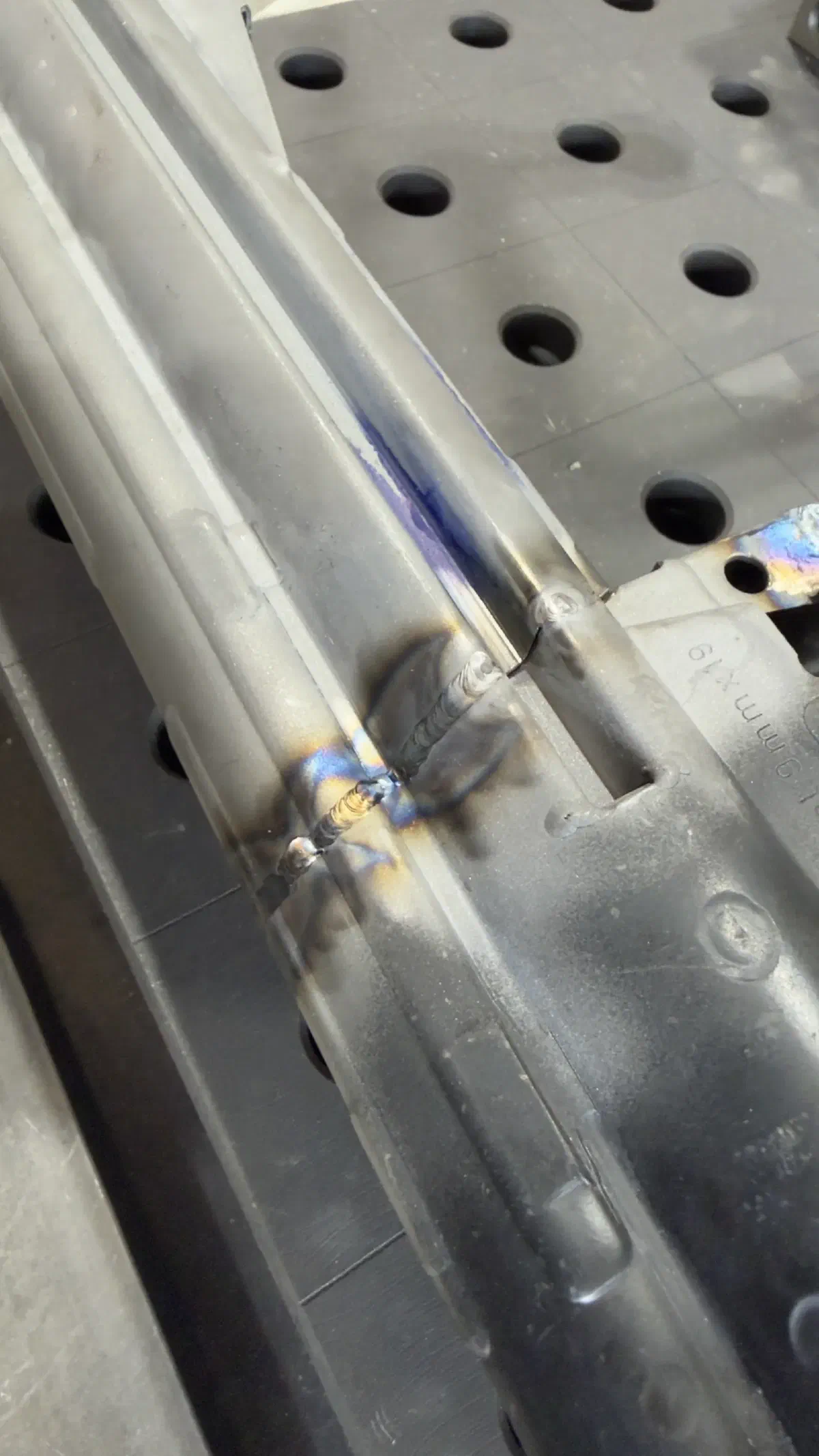
Why don’t I use copper or aluminum backers? Because both can spit up/introduce contaminants into the weld if I accidentally arc onto it. 1018 won’t; and the sheer mass of the like-material backer prevents it from ever sticking to the thin sheet steel around it. Also—I don’t have aluminum or copper backers. Why make two tools (one to form the shape; one to back the weld when you can just make one?)
The part is flipped upside down onto my bending jig (convenient holder)
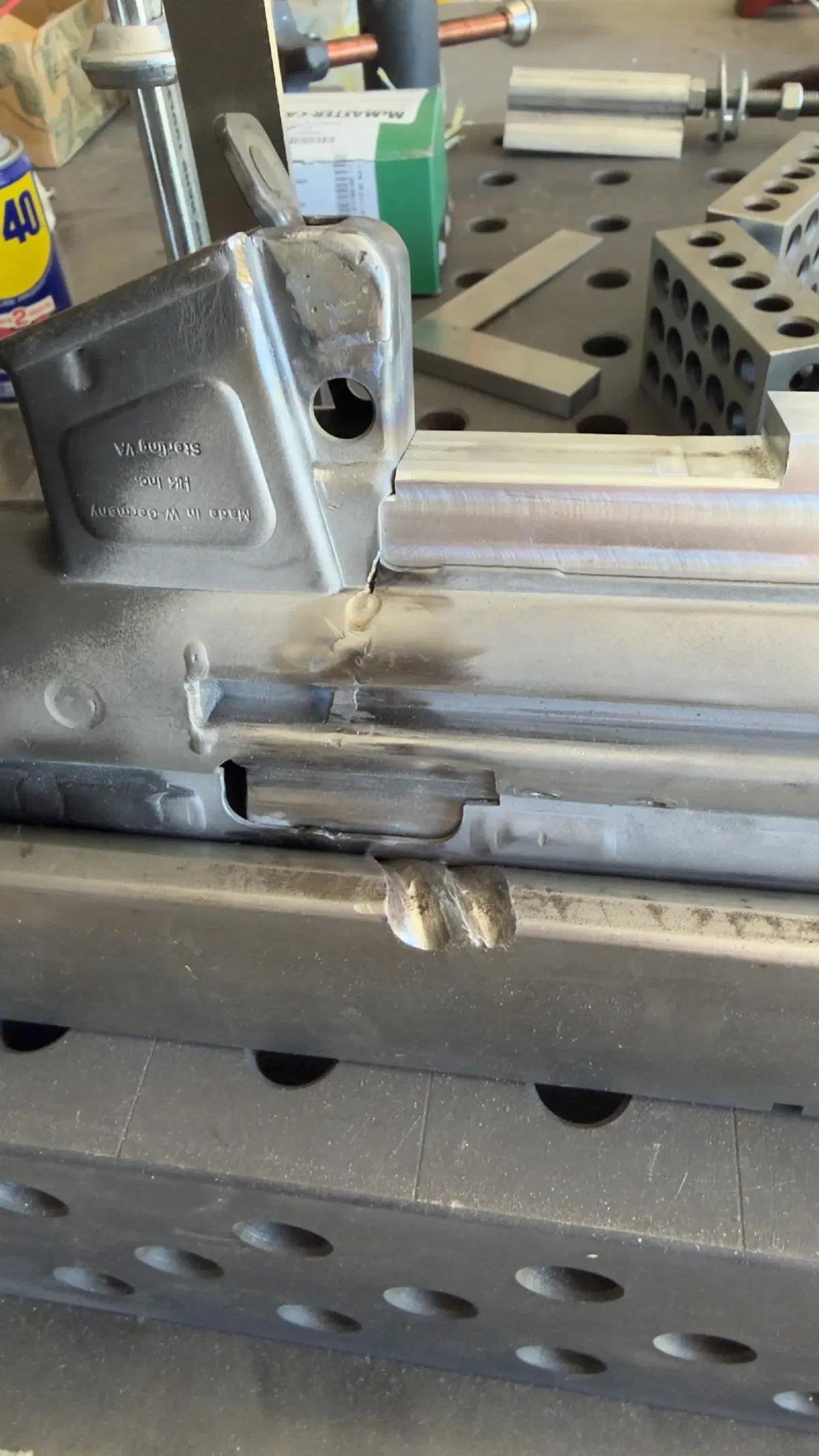
A backer is installed at the top to prevent burn-through at this small corner at the top.
Extra material is built up to allow myself something to sand down while dressing the weld.
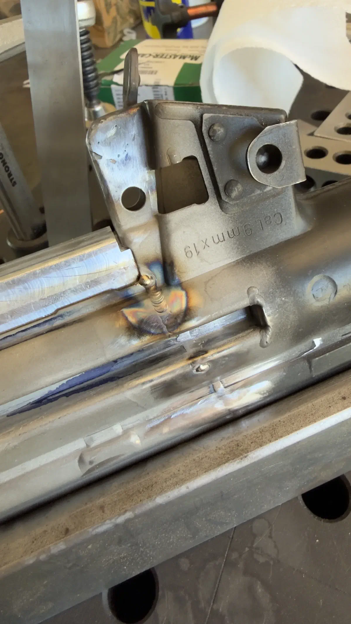
The inside of the welds are where it counts. Not all of mine pass initial inspection, which is extremely fucking annoying when it happens, because getting the mandrel in and out is a…procedure. It’s extremely hard to get this on camera; I’d need a dedicated macro lens, but the initial bead didn’t achieve full penetration in two locations, both in the center of the receiver channel where access is difficult and dimensions are critical as these are the primary surfaces the bolt carrier rides on. Tried to do some more photos but they’re legitimately unintelligible with the camera/light I have available. Bottom line: where the receiver contacts the mandrel, you get 0 protrusion into the the bolt carrier’s space. On the raised stamped areas/reinforcement ribs, the bead will protrude. Fortunately, this space is not currently being used by anyone except as reinforcement+“void” space for fouling to collect in. The mandrel ensures that weld never encroaches on space that’s needed by moving parts.
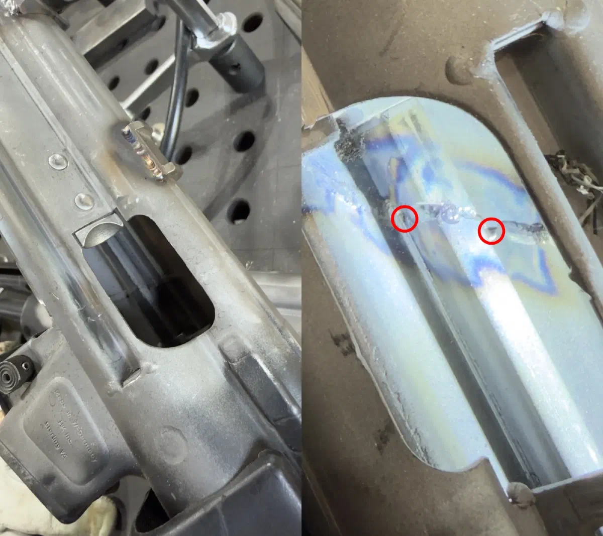
One receiver passed inspection. The other failed - looking in from the ejection port, I noted incomplete penetration in two critical areas.
Fortunately, mild steel sheet is nothing if not forgiving. No heat treat to worry about. I use a carbide bur to remove material on the outer side of each of these problem areas to allow me to penetrate through, then at 50A, lay another bead on top of the original, focusing on pushing extra filler in to build out the bead. When you’re building up an area with filler, remember that, on thin sheet steel, it acts in multiple dimensions– you might see it only on the side you’re watching, but it’s going to be building up close to the same protrusion on the opposite side.
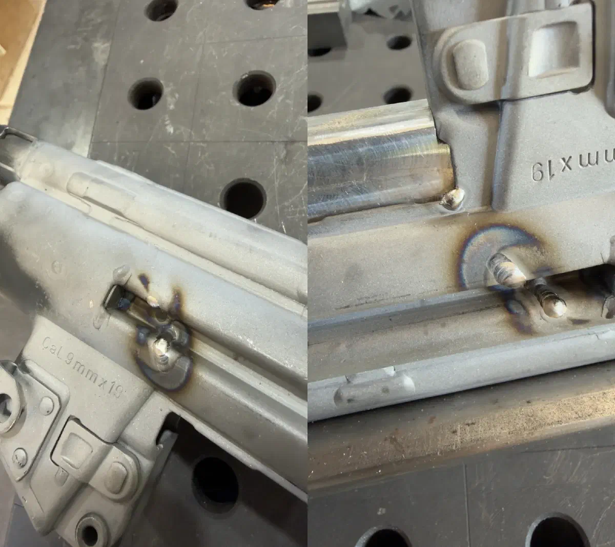
50A, 5A higher than previously, accounts for the fact that this is now a “flat” sheet of metal with no distinct edges to heat up/overheat. I still gouge the opposite side of the problem areas to help ensure I’m not just building up material on the outside, but 50A for this thickness of steel is more than sufficient to penetrate through to the back. I also take the opportunity to correct an aesthetic issue at the magwell corner from my initial execution that didn’t meet standard.
Work continued at the back end. I was really unhappy with Gigliotti’s work here as well on one of the receivers. I observed severe burn-through and poor MIG backfill, and the tabs on the flat were misaligned. When I build out MP5 flats, I prefer to use a reinforcement U-plate like in HK91s/HK93s–I just think it’s a cleaner, more precise way to do things. But, barring that option, there’s another way to solve things here. I don’t know if it’s the right way, or if it was even the most sensible way, but it’s what I did. It thematically fits a reweld build, too.
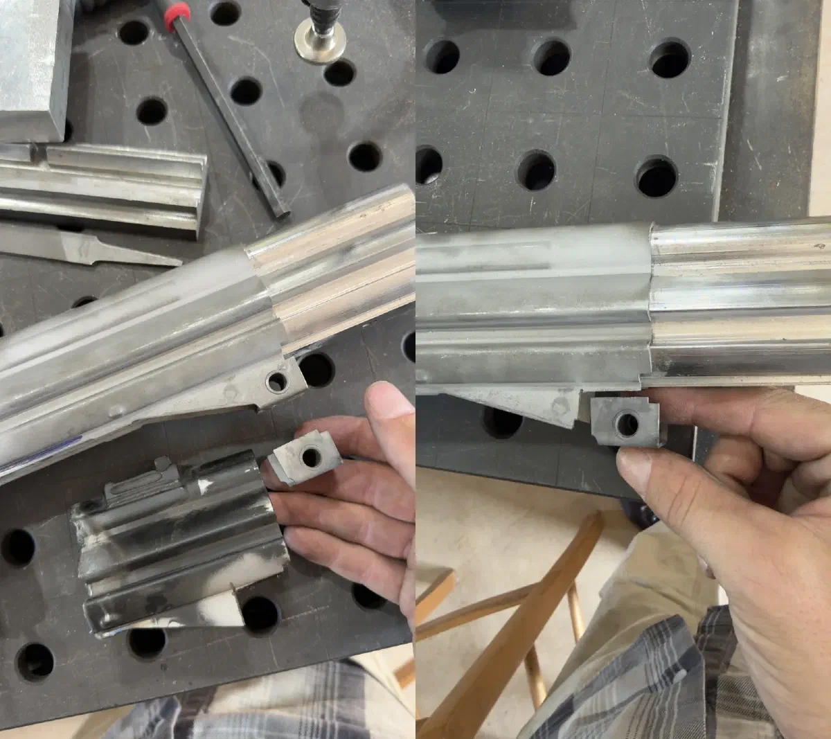
yeah, I’m going to take this little square chunk out of the original stub and put it on this new receiver.
Having decided that we are going to take this approach, of all things (I…probably should have just drilled out the original bushing, cut the old weld, redone it nicely minus misaligned tabs, welded in an HK93 style plate, then treated it like I would any build), we need a way to locate it at the exact distance from the center of the receiver, which is the datum that establishes the location of the bushing. So I whipped up a little block out of 1018 with some milled surfaces on top and bottom that meet this exact requirement.
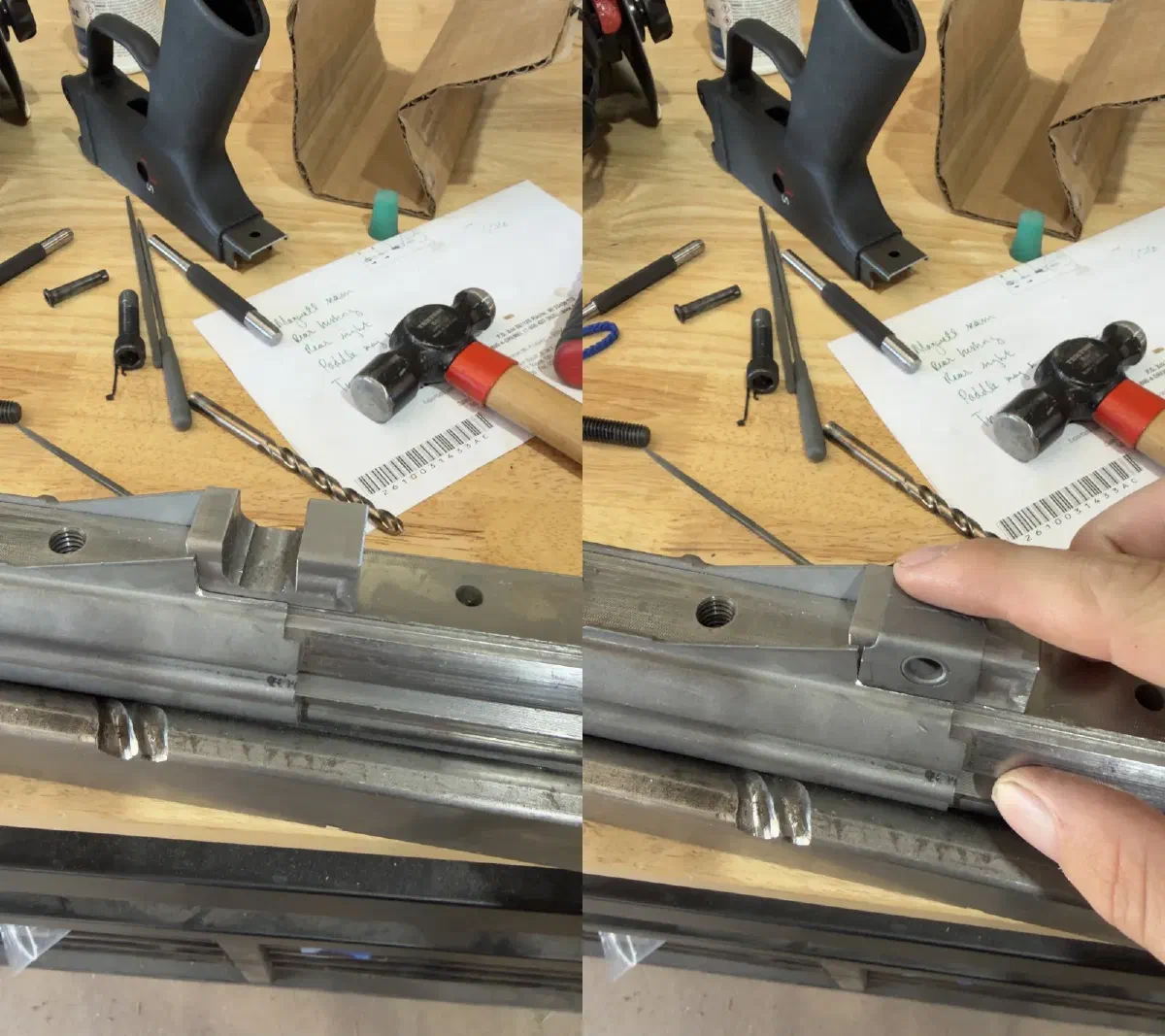
It helps having a mandrel in the gun. I never take it out for the entire process, usually–it just makes it far easier to hold than trying to rig up bizarre contraptions to hold a funny circle-thingy in a square vise.
The section is located on the xy axes by a 7mm dowel pin installed on my alignment block (also attached to the mandrel)
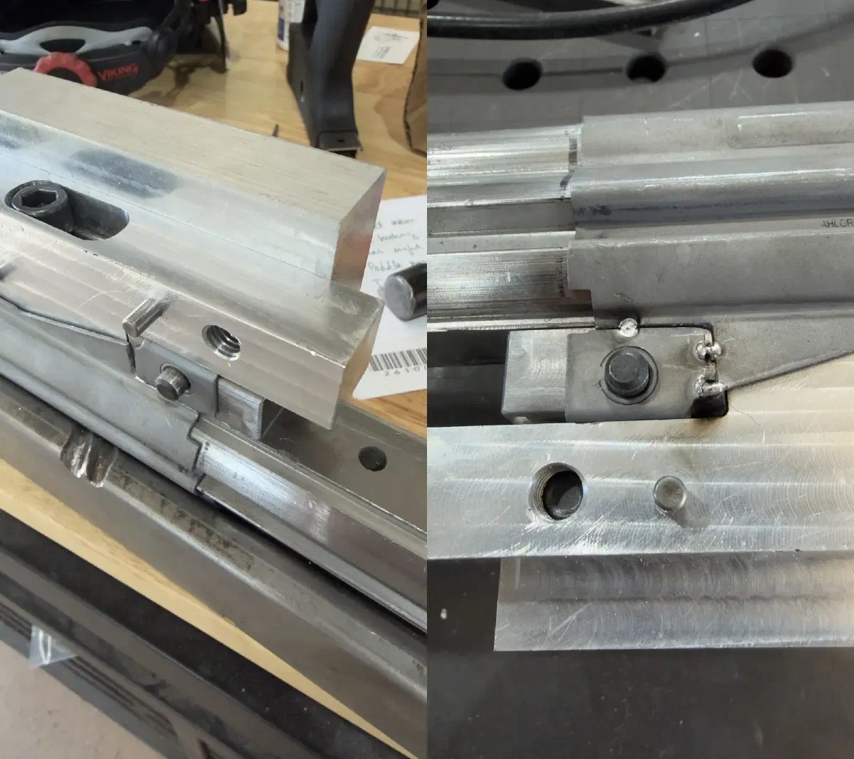
The center bit screws into the mandrel and has a face which indexes against the rear of the magwell, the datum for setting the xy pos of the bushing.
Once tacked and verified, both sides are welded. Effort is paid to push enough filler and heat in to ensure full penetration in both directions. Still keeping everything a nice silver-gold with blue only at the edges of my HAZ.
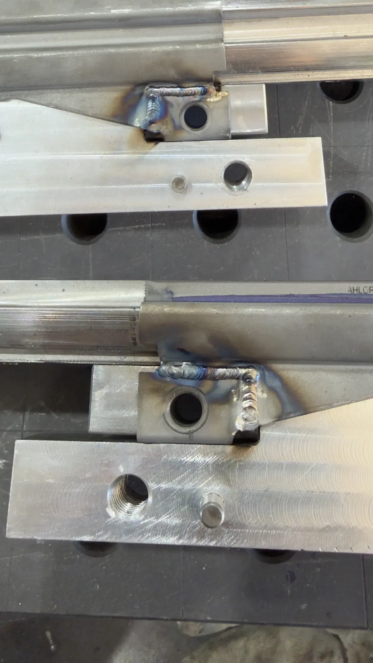
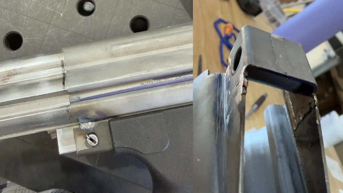
Final fitment check with a trigger pack, and verification of full penetration prior to final dressing and shaping of the edge profile.
Dressing begins.
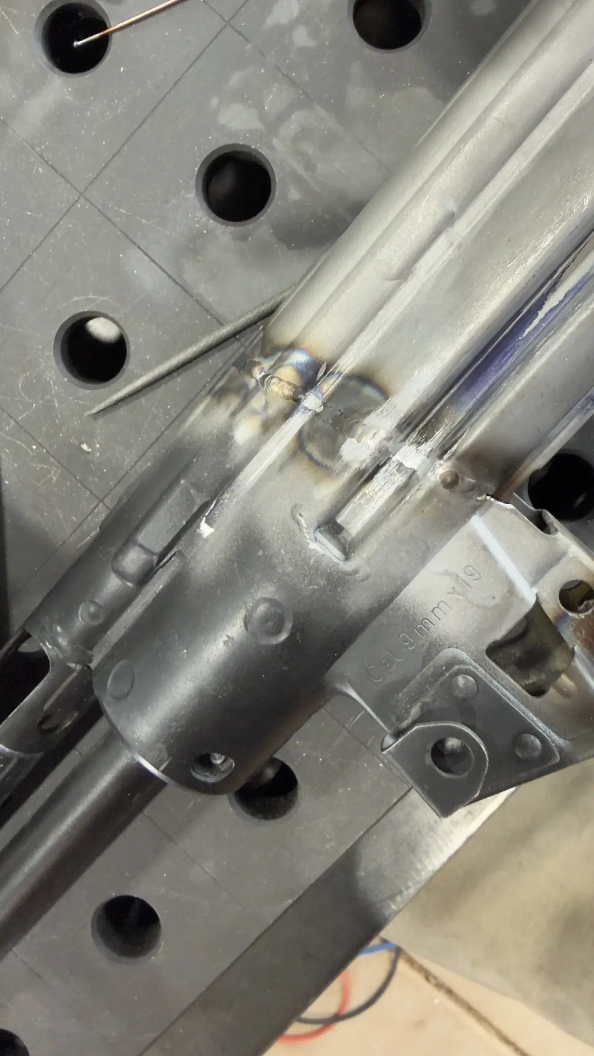
I have a collection of small flap wheels and Swiss files to maintain the contours of the creases in the stamping. There’s no escaping the tedium though. Put on a podcast and and don’t try to rush it.
And from here, business as usual. The semiauto shelf is TIG brazed in place, and the trigger housing clipped and pinned. Customer supplied an FRT; testing was complete with 200 rounds of 9mm demonstrating that the system was fully functional (if in need of a new extractor spring). We’ll now put these aside to prep for manganese phosphate and a moly resin topcoat.
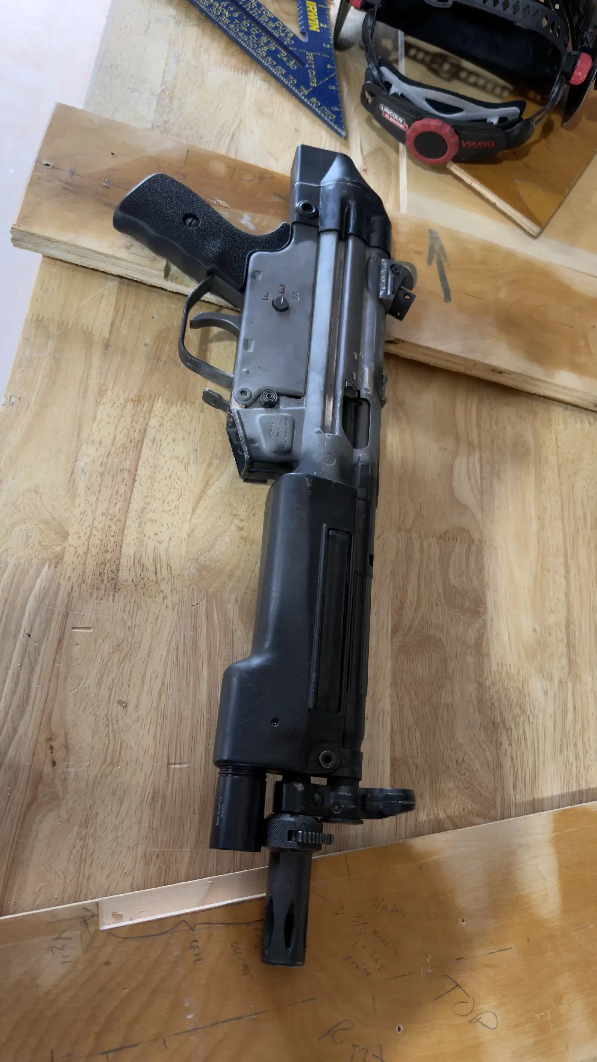
After being fully degreased and sandblasted with 80 grit aluminum oxide, the parts are immersed in a manganese phosphate bath. The chemical reaction, commonly known as parkerization, replaces the outer layer of steel with a spongy layer of hydrated manganese-iron hydrogen phosphate which readily accepts and retains oil or pigment. A phosphate coating does not intrinsically provide corrosion resistance, but in its bare form, retains oil very well, and as a base layer, increases the adhesion of the topcoat to the underlying steel.
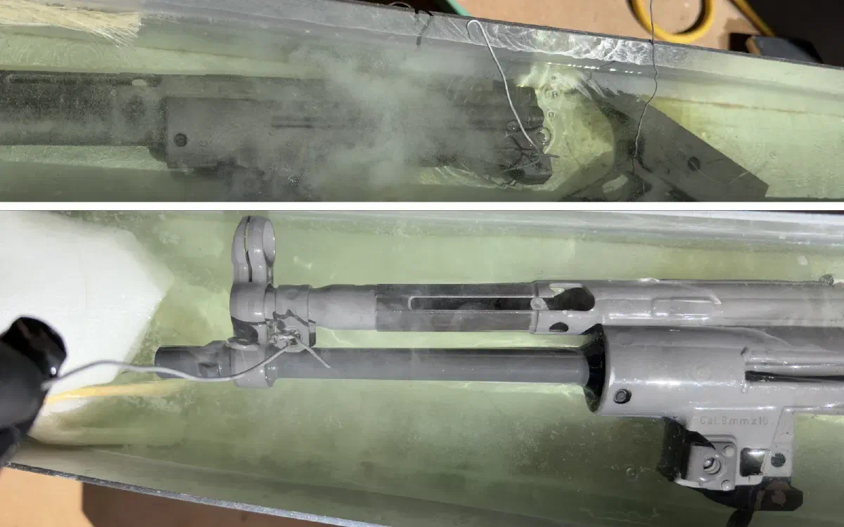
The parts are then sprayed with semi-gloss black Moly Resin with an HVLP touch-up gun, and placed into the oven to cure for one hour at 300F.
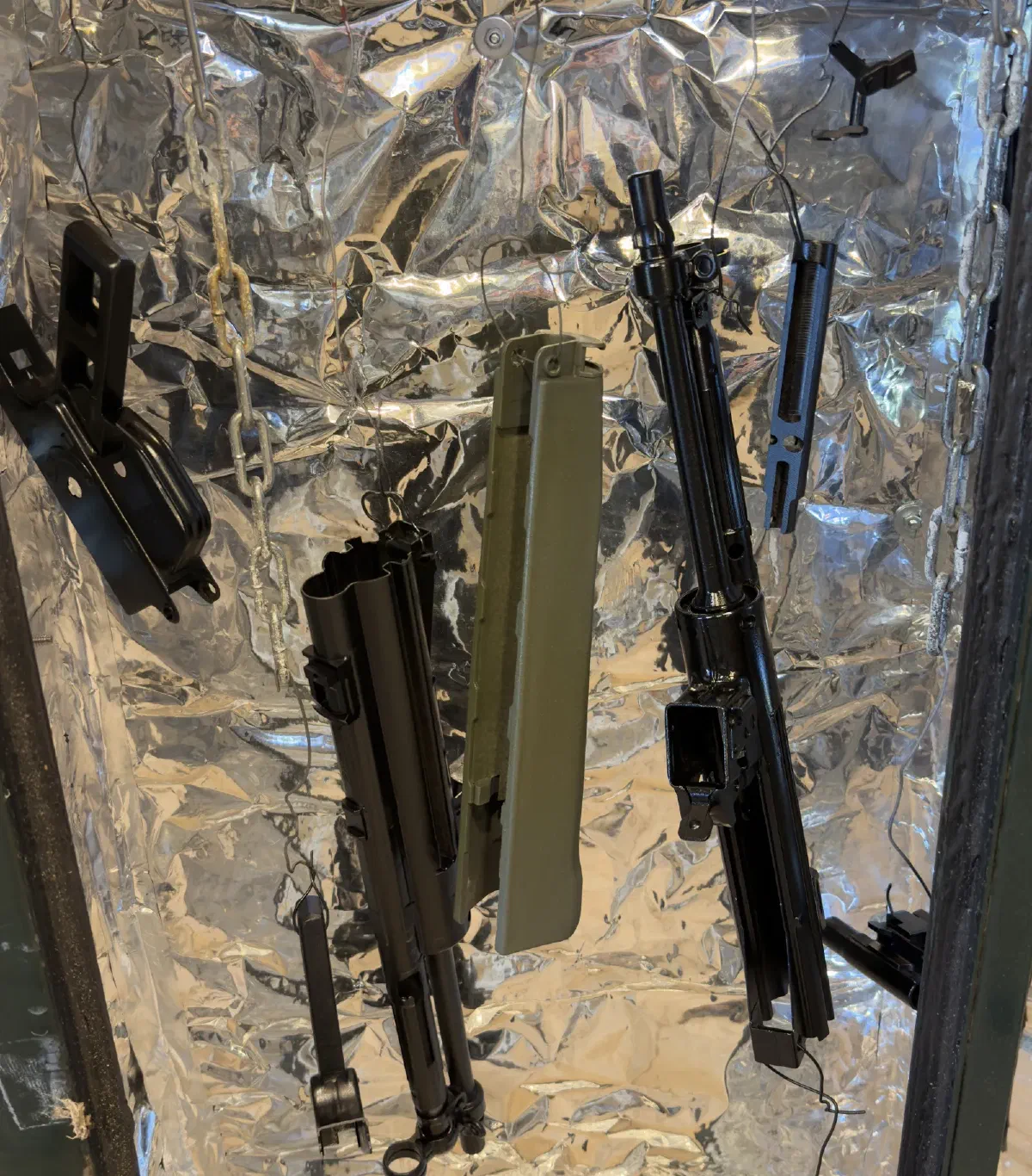
We assemble, test fit, and enjoy the result.
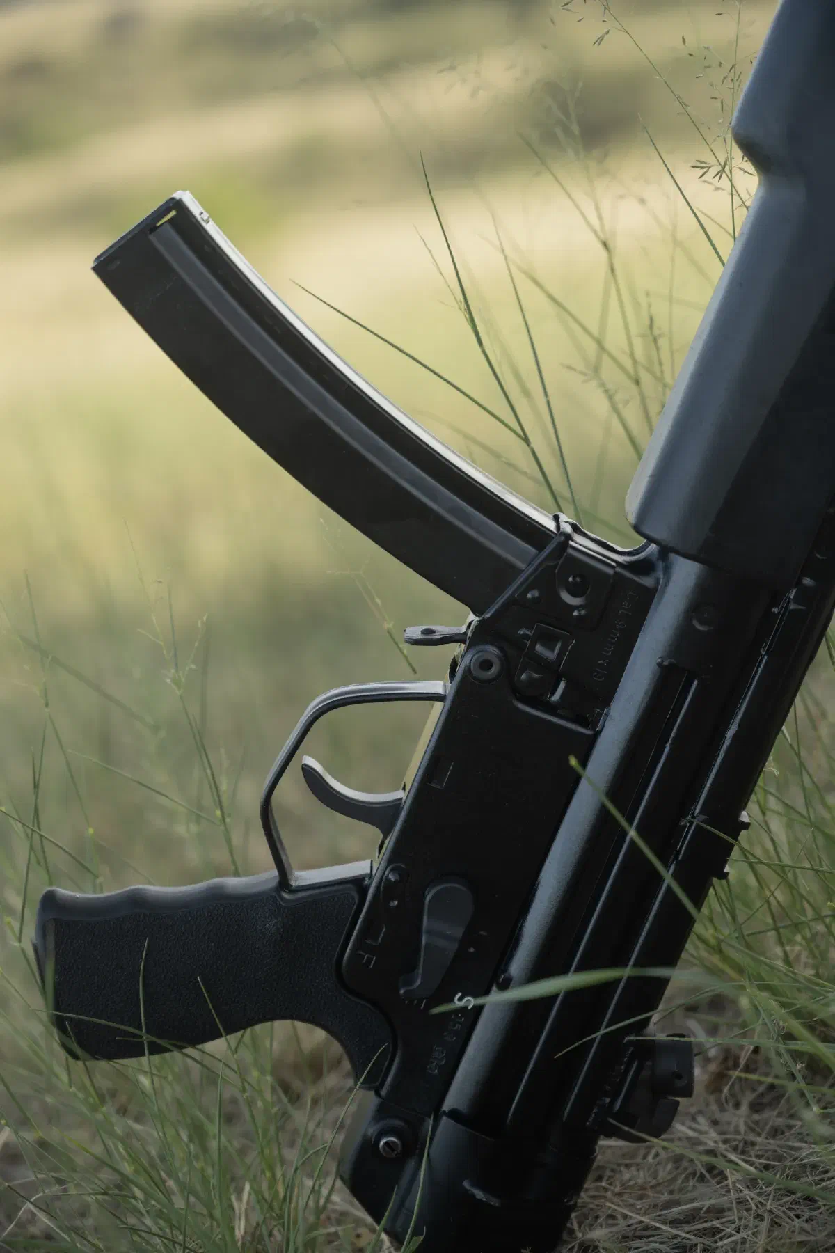
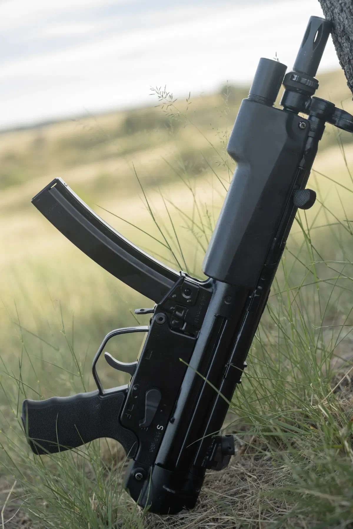
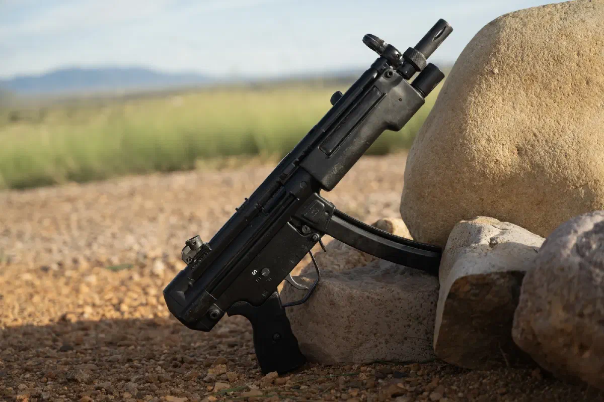
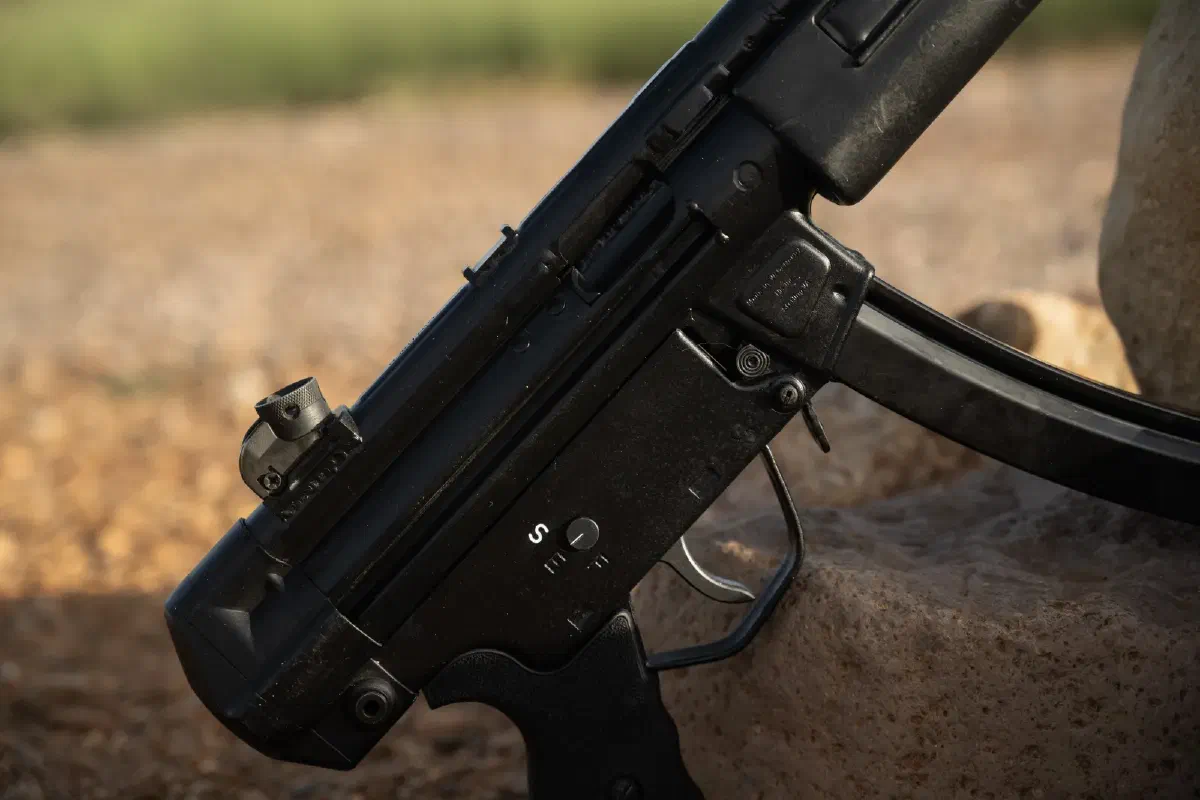
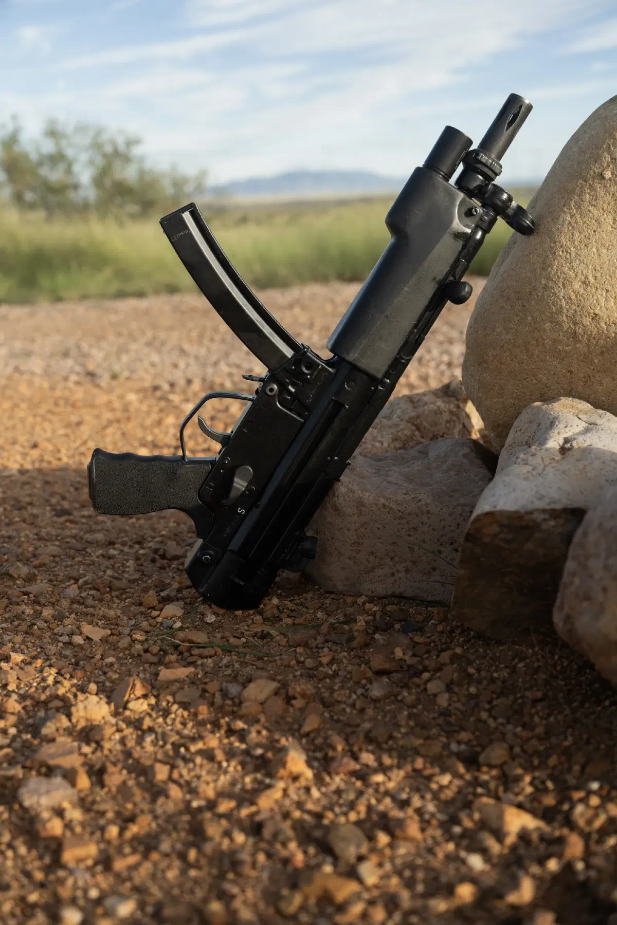
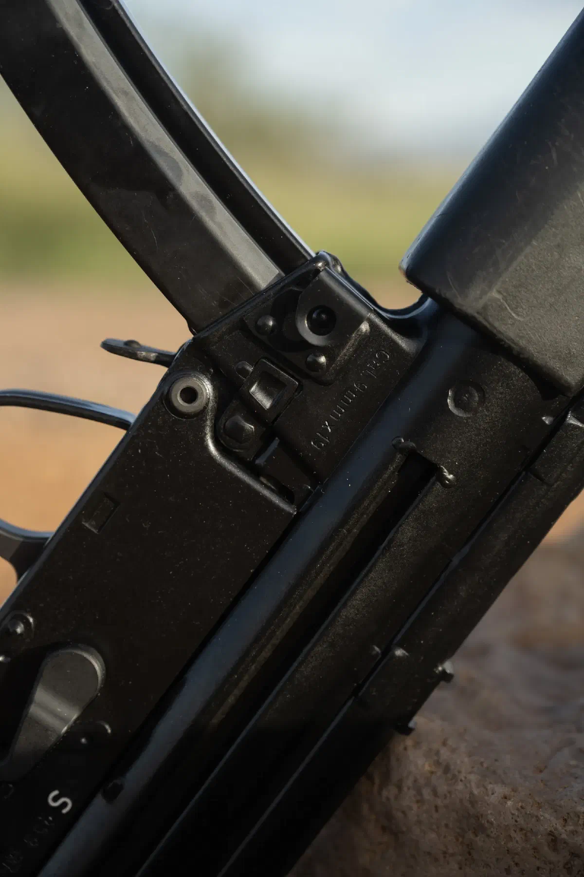
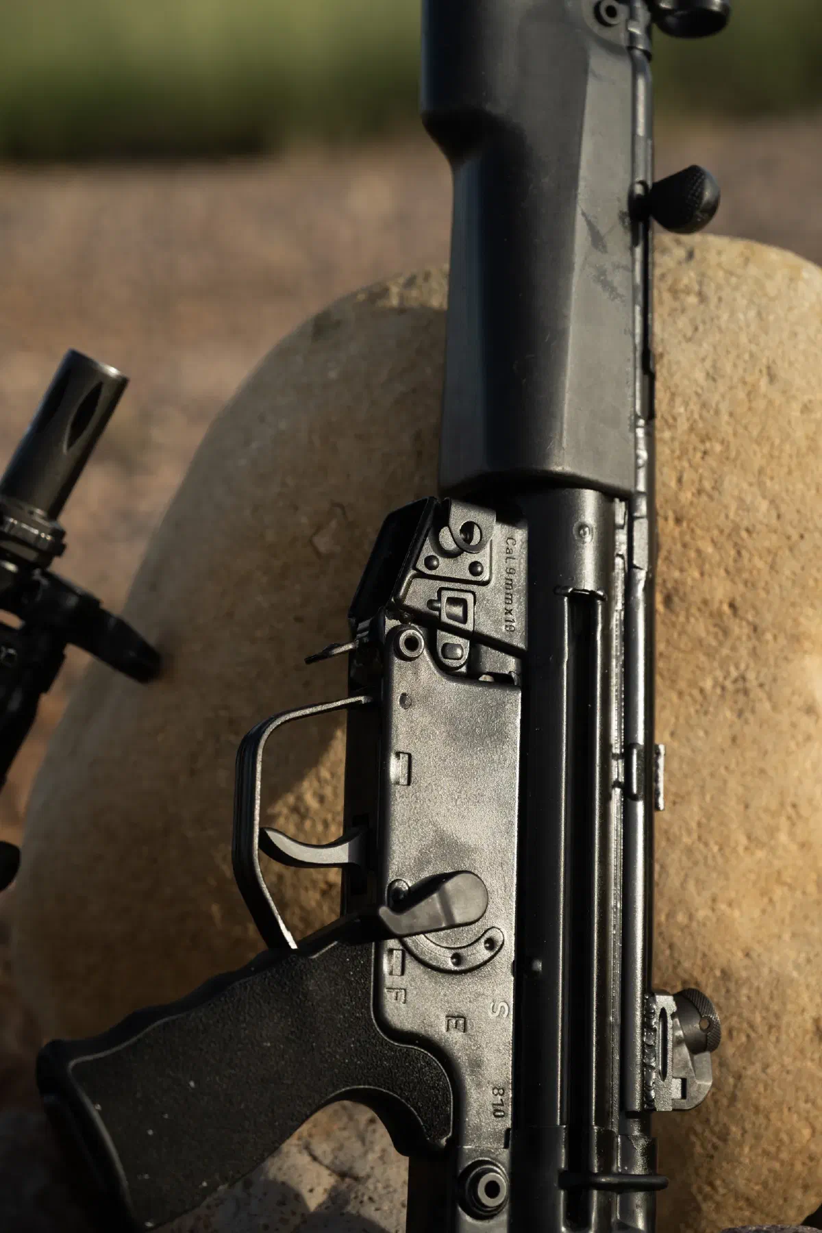
Want me to build you a roller gat like this one (or maybe something else?) My order book is open - click here.
Note: I no longer produce the above mentioned forming mandrels and dies for customers due to the constraints of my current machines—I sold the Haases with the rest of my machine shop when I went active duty—but I have published the CAD files of the mandrels on my site for those that have the machining capability (or know a guy with a shop). Please see: Marble Duck — HK G3 and MP5 Straightening Mandrel Designs and Specifications